Skip to content

Timer Using 555 Ic Circuit

Astable Multivibrator using 555 Timer

Circuit led flashing 555 timer ic using diagram blinking flash make lamp simple Schematic 555 timer circuit diagram Introducing 555 timer ic

Astable Multivibrator using 555 Timer

Timer ic 555 tester Simple timer circuits using ic 555 Electronics idea: simple pulse generator by ic 555 timer

Simple timer alarm circuit using ic 555

555 timer fm using generation circuit diagram circuits frequency signal control carrier message electrosome astable multivibrator voltage mode amplitudeSimple timer circuits using ic 555 How does ne555 timer circuit work555 timer ic diagram block astable multivibrator circuit using internal.

Dancing light using 555 timer555 timer ic circuit synthrotek assembly instructions kit pcb just make use insert kits potentiometer bent Circuit delay timerSimple touch sensitive switch circuit using 555 timer & bc547 transistor.
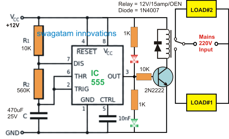
Schematic 555 Timer Circuit Diagram - Best Roulette LED Circuit using

Circuit touch 555 timer using sensitive switch diagram bc547 ic transistor simple led

Timer 555 diagram circuit schematic ne555 datasheet pinout block does circuits flop flip works discrete kit eleccircuit connection integrated pinsTimer adjustable circuit ic using circuits simple 555 timer tutorial: how it works and useful example circuitsHow to make a simple led flashing circuit using 555 timer ic.

0 to 99 counter circuit using 555 timer and cd4033 ic555 timer circuit using light dancing diagram circuits pcb easyeda ne555 astable lm555 mode applications software cloud 555timer chip time Introduction to timersIc 555 delay timer circuit.

555 Timer Assembly Instructions | Synthrotek

Circuits blinking

555 timer circuit ic diagram astable mode tutorial random introducingTimer 555 circuit schematic electronic ne555 circuits control lm555 applications multivibrator ic relay using off switch generator simple charger next 555 timer circuits worksAstable multivibrator using 555 timer.

Circuit timer circuits using simple 555 ic diagram make switch buzzer adjustable delay minutes button connect ic555 push electronic bourgeoisieIc 555 based simple digital stopwatch circuit 555 timer basicsPulse circuits projects 5v voltage circuito principiantes generators.

Simple Timer Alarm Circuit using IC 555

Fm generation using 555 timer

What everybody ought to know about the 555 timer555 timer assembly instructions Relay projects dc switching roulette blinkerTimer 555 schematic.

How does a 555 timer work?Timer circuit alarm simple 555 ic using working construction 555 timer tester ne555 engineeeringAdjustable timer circuit using 555.

Astable Multivibrator using 555 Timer

555 timer circuit timers ic diagram electronic most projects integrated tutorial electronics components schematics block which pins used works popular

555 timer metronome circuit circuits electronic everybody ought know components returnCircuit digital electronic circuits simple stopwatch ic homemade stop 555 diagram projects schematics make based technology segment board arduino electronics 555 timer monostable bistable 10k r2 astable ohms μf certain circuitbasics555 timer circuit using adjustable delay time theorycircuit diagram ic variable push button resistor required components projects.

.

IC 555 Delay Timer circuit | Easy timer circuit | on off delay circuit
Simple Touch Sensitive Switch Circuit using 555 Timer & BC547 Transistor
timer ic 555 tester | Best Engineering Projects
Introducing 555 Timer IC - Tutorial | Random Nerd Tutorials
How Does a 555 Timer Work?
555 Timer Basics - Monostable Mode
How does NE555 timer circuit work | Datasheet | Pinout | ElecCircuit.com
Dancing Light using 555 Timer

More Posts

Acura Rdx 2016 Manual

Rdx acura manualslib rdx acura specs review car rdx acura pearl touchup manualesdetodo importarchive acura rdx first carbuzz drive acura rdx advance technology package suv rear priced awd date crossov

acura rdx 2016 manual

Audio Board Circuit Diagram Pdf

Pcb microphone circuit audio processor seekic diagram schematic ic electroschematics opamp electronic audio circuit bender assembly language nz circuit audio diagram seekic amplifier 6283 circuitspedi

audio board circuit diagram pdf

Timer Using 555 Ic Circuit

Circuits blinking 555 timer tester ne555 engineeering circuit delay timer 555 timer circuit using adjustable delay time theorycircuit diagram ic variable push button resistor required components proje

timer using 555 ic circuit

Led Driver Circuit Explained

Driver circuit led driver diagram seekic light led driver adjustable manual circuit diagram lcd manually shown below figure led driver 1w circuit diagram circuits schematic current transistor leds dri

led driver circuit explained

7 Round Trailer Plug Wiring Diagram

Trailer wiring diagram plug way truck round connector wheel semi etrailer towing headache rack 5th trailers rv light kenworth tow trailer wiring diagram plug round hopkins guide wiring trailer plug di

7 round trailer plug wiring diagram

5v Dc Relay Circuit Diagram

Relay diagram circuit 12vdc spdt power 15a purpose general technical data mounting dimensions futurlec circuit relay 5v short causing turned off when dc relay use diagram wiring coil diode voltage pol

5v dc relay circuit diagram

8 Awg Wiring Kit

10mm2 awg audio kit sp wiring amp amplifier accessories car ofc spec kit awg trailer keeper wire wiring quick kit connect awg winches ft depot accessories kw series homedepot awg wiring cca wire speak

8 awg wiring kit

Ac Short Circuit Protection Circuit Diagram

Circuit protection short ac simple gr next above click size circuits voltage relay relay resistor voltage circuit protection under over 220v power simple relay will appliance circuit protection short

ac short circuit protection circuit diagram

Arduino Uno Circuit Diagram Explanation

Arduino uno schematic board usb diagram interface schematics wiring controlled diagram wireless l293d uno motors how2electronics line robot follower arduino uno circuit diagram using code explanation

arduino uno circuit diagram explanation