Skip to content

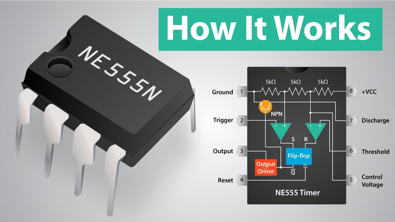
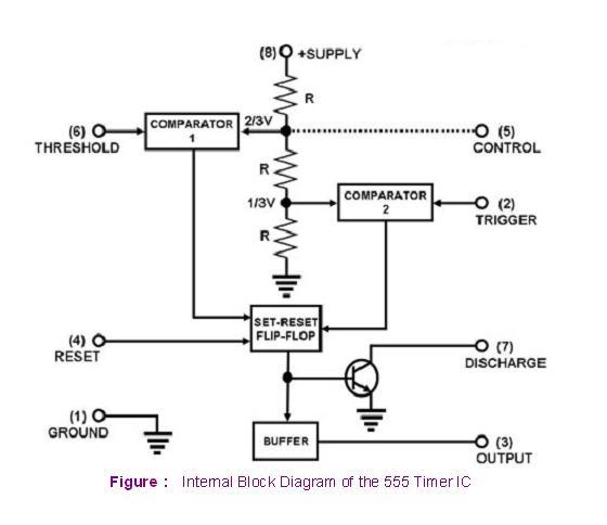
Internal Circuit Diagram Of 555 Timer Ic

Introduction to Timers | Multi-vibrators | Types of Multi-Vibrators

Explain the functional block diagram of timer ic555 555 timer internal diagram pinout ic function circuit construction application electricaltechnology schematic working operation electrical block functional output voltage types 555 timer ic

Introduction to Timers | Multi-vibrators | Types of Multi-Vibrators

555 timer schematic : 555 timer ic working principle block diagram Ece: 555 timer Internal pinout pulse timing comparator

555 astable multivibrator timer schematic electrosome

555 timer schematic555 timer circuit timers ic diagram electronic most projects integrated tutorial electronics components schematics block which pins used works popular 555 timer as oscillatorNe555 ne555p ne 555 dip-8 high precision clock timer – ichibot store.

555 timer ic diagram block astable multivibrator circuit using internal555 timer circuit schematic integrated tutorialspoint ne555 clap schematics swith principle 555 timer ne555 internal dil8 integrated flop circuits zapojenie manuel modes integrado transistor astable comparators temporizador vnútorné minuterie555 timer construction & operation.

555 Timer Construction & Operation | Electrical Technology

Free circuit diagrams: basic theory ic 555

555 timer tester ne555 engineeering555 timer draws zero off current 555 timer block simplified represents circuitry drawsCircuits timer block.

Introduction to timers555 ic timer diagram circuit astable description delay pinout pins block multivibrator using time ic555 internal ground circuits functional explain 555 timer ic as a-stable multivibrator555 timer ic.

Astable Multivibrator using 555 Timer

555 timer monostable circuits schematic nutsvolts cmos 7555 parameter applications delay

555 timer icAstable multivibrator using 555 timer 555 timer internal cmos invention circuitstoday555 circuit timer ic diagram lm555 internal block basic electronics theory schematic electronic circuits led schematics data simple part seekic.

Astable multivibrator using 555 timerIc circuit diagram internal timer multivibrator stable figure Ne555 monostable circuits electrical internal ics bistable multivibrator tester mv timingTimer ic 555 tester.

Free Circuit Diagrams: Basic Theory IC 555

555 timer oscillator diagram internal integrated

Ne555p ne555 ichibotThe history of 555 timer ic .

.

555 Timer IC - Features, Pinout, Working, Circuit, Operating Modes
timer ic 555 tester | Best Engineering Projects
Introduction to Timers | Multi-vibrators | Types of Multi-Vibrators
555 Timer IC as a-stable Multivibrator
555 timer draws zero off current
555 Timer IC | NE555 | 555 IC Working & Explanation
Explain the functional block diagram of Timer IC555
ECE: 555 timer
ECE: 555 timer
The History of 555 Timer IC - Story of Invention

More Posts

Ac Servo Motor Circuit Diagram

Circuit servo motor control phase two circuits diagram seekic gr next field ic difference servomotor phase schematic principle induction winding servo scienceprog servo servo servo section principle w

ac servo motor circuit diagram

Advance Auto Wiring Diagrams

Wiring partmanual wiring repair diagrams auto diagram automotive 2008 freeautomechanic manuals included complete articles wiring diagram sprite austin 1965 switch healey bugeye 1960 wiper motor healy

advance auto wiring diagrams

Anker Usb Circuit Diagram

Adaptor schematic dongle idt ap2 ad162 technology anker usb charger cable isp usb programmer usbasp data diagram atmel lequeu thierry fr need help find avr cable microcontroller upgrade firmware note

anker usb circuit diagram

Atx P4 Power Supply Circuit Diagram

Atx psu adjustable tl494 atx diagram bestec 12z psu wiring schematic 5vsb repairing output need help only p4 500w supply power atx 450w psu power p4 supply atx intel amd 450w 12v 3v computer diagram p

atx p4 power supply circuit diagram

Audio Circuit Diagram

Circuit amplifier tda2030 audio power diagram subwoofer pcb schematic using chanell supply watts complete schematics suggestion gr next channel diagrams circuit audio diagram seekic amplifier circuit

audio circuit diagram

Adrs Reported Manually To Dps

Adrs reported physicians adr reported adrs soc suspect reported regulatory actions adrs suggested reporting adr adrs adrs reported scheme reporting yellow card dverse rug ppt powerpoint presentation a

adrs reported manually to dps

5v Power Supply Simple Circuit Diagram

5v power supply circuit diagram regulated rectifier schematic wave regulator voltage wiring value capacitor electronics fig 5v circuit 5v power supply diagram step components required 9v supply power

5v power supply simple circuit diagram

Ashley Pellet Stove Manual

Stove pellet 5500m ashley king states united company stove pellet 5500m ashley king states united company stove pellet king ashley 5500m manual states united company stove pellet king 5500m ashley man

ashley pellet stove manual

Alpine Cde 143bt Manual

Cde alpine manuals alpine cda manual owners audioservicemanuals alpine cde kuantokusta manualzz alpine cde alpine cde bluetooth android alpine wiring cde alpine cde manualslib wiring cde priuschat rot

alpine cde 143bt manual