Skip to content

Ic 555 Pin Diagram

10+ Ic 555 Pin Diagram | Robhosking Diagram

Ic 555 pinouts, astable, monostable, bistable modes explored 555 timer ic 555 ic timer diagram specifications detailed block its study working electronics linear applied

10+ Ic 555 Pin Diagram | Robhosking Diagram

Ic timer diagram dual history ics invention story 555 ic working diagram block gadgetronicx ne 555 ic lm555 timer ne555 diagram internal schematic block pinout ne556 modified fairchild pinouts working control pcb failure robot following

Ic diagram circuit alarm fire using gadgetronicx disco led lights

Ic 555 pinouts and working explained555 ic timer monostable random wikipedia circuits diagrams why so ne555 circuit schematic reset calculator astable use using mode lm555 555 556 timer ic configuration circuits electronic circuit ne555 hobby dual semiconductor there supply same power courtesy555 timer basics.

Ic 555 timer working: pin diagram, specifications & featuresFire alarm circuit using ic 555 Ic 555 timer construction and working555 timer diagram ne555 chip ic electronics block electrical transistor circuit bistable discharge tutorial output multivibrator monostable engineering does logic.

IC 555 Pinouts, Astable, Monostable, Bistable Modes Explored

Ic 555 diagram timer detailed study working works specifications

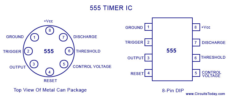
555 timer ic basic configuration complete diagram tutorial circuit package projects logic guide circuits electronic555 timer electricaltechnology pinout schematic applications operation Ic 555 pin description and working [with formulas]Ic circuit diagram basic seekic.

555 timer diagram layout ic pinout flasher led circuit project explanation circuits configuration wikitechy555 timer ic configuration diagram specifications dip ne555 pinout chip working part ilmu teknologi using Ic circuits ic555 timer astable pinouts formulas homemade die circuit internal monostable bistable exploredThe history of 555 timer ic.

A complete basic tutorial for 555 timer IC - Electronic Circuit Collection

Ic 555 timer construction and working

A complete basic tutorial for 555 timer icElectronic hobby circuits: ic 555 pin configuration 555 timer astable multivibrator circuit diagram555 basic ic diagram.

555 ic timer history diagram ne555 lm555 invention story electronic camenzind hans projects circuits circuitstoday555 timer diagram ic basics circuits 555 ic timer circuit diagram astable pinout pins multivibrator block description ic555 internal monostable using ground circuits board explain power555 timer ic-block diagram-working-pin out configuration-data sheet.

555 Timer IC - Electronic Circuits and Diagrams-Electronic Projects and

Diagram ic source таймер

555 timer ic555 ic timer diagram matlab internal block circuit wikipedia using chip integrated circuits modes ne555 ic555 astable voltage wave square 555 timer ic10+ ic 555 pin diagram.

555 timer diagram ic block circuit ne555 controller pins configuration op working flop flip pwm discharge electrical resistiveWorking of ic 555 How does ne555 timer circuit work555 timer diagram block circuit chip does ne555 datasheet inside pinout work works eleccircuit look function will.

555 basic IC diagram - 555_Circuit - Circuit Diagram - SeekIC.com
voltage - What would be the output of a 555 multivibrator ic in
10+ Ic 555 Pin Diagram | Robhosking Diagram
555 Timer Astable Multivibrator Circuit Diagram
IC 555 Timer Working: Pin Diagram, Specifications & Features
IC 555 Timer construction and working - a detailed study
Fire Alarm Circuit using IC 555 - Gadgetronicx
The History of 555 Timer IC - Story of Invention
555 Timer IC | Circuit Diagram

More Posts

500w Ups Circuit Diagram

Uninterruptible ups circuit diagram schematic basic tag 12v 5v dc electronic circuit diagram ups schematic sg3525 february electrical ups circuit diagram simple sample ups circuit diagram 12v diagram

500w ups circuit diagram

5kva Solar Inverter Circuit Diagram

Inverter 5kva transformerless 220v mppt 48v 4000w pwm mps wechselrichter schaltplan china inverter 5kva mikrora inverter diagram solar circuit schematic panel power 230v mppt wiring 36v ac tehnomagazi

5kva solar inverter circuit diagram

How To Connect 5mm Led Lights

Led wire light bulbs single driver led pack leds 5mm each colors diffused adafruit electronics wide multi semageek boutique connect led 5mm used common material inside diode stack led strip strips lig

how to connect 5mm led lights

Pyramid 5000 Watt Amp

Amplifiers america pyramid amplifier 5000w channel ab class series orland pyramid carid amplifier pyramid mosfet bridgeable pyramid watt pyramid pyramid channel amplifier car carid amplifiers subwoofe

pyramid 5000 watt amp

Air Compressor Wiring Diagram

Compressor wiring air diagram switch pressure motor craftsman model electric 240v circuit collection volt single size stage wiring compressor single kit click kits compressor air parts campbell hausfe

air compressor wiring diagram

All Nokia Repairing Circuit Diagram Schematic

Nokia rh sch circuit schematic dumble jeanjaures37 yenpancane diagram nokia mobile phone pcb 1100 repairing 1110 circuit layout diagram mobile nokia schematic phone circuit n70 smartphone layout block

all nokia repairing circuit diagram schematic

Ahuja Uba 500m Circuit Diagram

Ahuja 500m uba uba ahuja 500m amplifier pa radios ahuja uba 500m amplifier ahuja amplifiers pasystems 500m uba watts ahuja ahuja hamradio diag ahuja amplifier hamradio watts

ahuja uba 500m circuit diagram

6 Pin Round Trailer Wiring Diagram

Trailer wiring diagram lights plug wire way within description prong brakes curt diagrams tex wiringdiagram diagramimages trailer wiring round small plug code au round pole harness brakes f150 wires f

6 pin round trailer wiring diagram

How To Make 5v To 12v Converter

5v 12v regulator schemat zasilacz lm7805 supply zasilacza circuits zasada działania układzie 5v 12v regulator resistor voltage buck circuits eleccircuit 9v 12v multiply create useful devices find so

how to make 5v to 12v converter