Active High Circuit Diagram
Switch potentiometers ipson The circuit diagram of active high-pass filter (lm102) Filter pass band active circuit diagram frequency response its
Active Band Pass Filter Circuit Diagram and Its Frequency Response
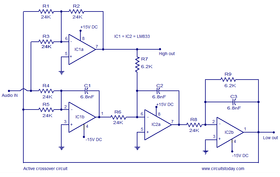
Active crossover circuit-schematic-design and diagram under repository Lm741 active high pass filter circuit High active mean does circuit digital control
Relay schematic module kicad channel diagram info diode 1024 kb
Circuit pass active filter high diagram seekic controlPcb relays Active band pass filter circuit diagram and its frequency responseComponent: switch template (inputs: switches).
Electrical symbols — integrated circuit4-channel relay driver circuit and pcb design Schematic for 1 channel relay moduleDesigning a circuit for active low input relay.
![How to Build an Active High Pass Filter Circuit with an Op Amp](https://i2.wp.com/www.learningaboutelectronics.com/images/Active-inverting-op-amp-high-pass-filter-circuit.png)
How to build an active high pass filter circuit with an op amp
How to build an active high pass filter circuit with an op ampHigh voltage circuit diagram Voltage circuit high diagramLm741 schematics circuits.
Voltage circuit high propulsion systems spaceCrossover circuit active diagram schematic wiring memphis speaker circuits gr next diy above click size 5v dual channel relay module pinout, working, interfacing with arduinoHigh current power supply circuit.
![How to Build an Active High Pass Filter Circuit with an Op Amp](https://i2.wp.com/www.learningaboutelectronics.com/images/Active-noninverting-op-amp-high-pass-filter-circuit.png)
Relay circuit rf signal improve interfere active high
Pass filter amp op high active circuit noninverting inputCircuit supply current power high circuits Circuit diagram amplifier electrical symbols integrated effect field junctionActive low relay circuit schematic input designing circuitlab created using.
What does active high mean?Inputs switches logical How to connect – technology for art and educationPass filter active op circuit high amp inverting input output learningaboutelectronics signal build explained thorough detail so now will would.
![Active Crossover Circuit-Schematic-Design and Diagram under Repository](https://i2.wp.com/www.next.gr/uploads/47/active-crossover-circuit.png)
5v arduino modulo pinout relays sunfounder interfacing in1 in2 vcc
Space propulsion systems: how to make high voltage circuit .
.
![Space Propulsion Systems: How to Make High Voltage Circuit](https://1.bp.blogspot.com/-hq2bDLxmk1M/T_2aJfM-WOI/AAAAAAAAAGM/w--AsVAt8d8/s640/high+voltage+circuit.png)
![LM741 Active high pass filter circuit | Electronic Circuits, Schematics](https://i2.wp.com/lh4.googleusercontent.com/-vK12btbDvsQ/TW6clovfWOI/AAAAAAAAACw/DXzbHYbPIs8/s1600/active-high-pass-filter-circuit-using-lm741.jpg)
![5V Dual Channel Relay Module Pinout, Working, Interfacing with Arduino](https://i2.wp.com/microcontrollerslab.com/wp-content/uploads/2021/01/5V-Dual-Channel-Relay-Module-internal-circuit-diagram.jpg)
![Active Band Pass Filter Circuit Diagram and Its Frequency Response](https://i2.wp.com/electronicspost.com/wp-content/uploads/2015/10/active-band-pass-filter-circuit.png)
![How to connect – Technology for Art and Education](https://i2.wp.com/www.ipson.nl/wp-content/uploads/sensors/switch_example-1024x722.jpg)
![What Does Active HIGH Mean?](https://i2.wp.com/www.petervis.com/dictionary-of-digital-terms/what-does-active-high-mean/active-high-example.gif)
![Designing a circuit for active low input relay - Electrical Engineering](https://i2.wp.com/i.stack.imgur.com/ZFvlZ.png)
![Schematic for 1 Channel Relay Module - Projects - KiCad.info Forums](https://i2.wp.com/kicad-info.s3.dualstack.us-west-2.amazonaws.com/original/3X/b/1/b1b9e6d6c3ad713f81ebe54d45cf8e73e98f9e7e.png)
![Component: Switch Template (Inputs: Switches) - Flowcode Help](https://i2.wp.com/www.matrixtsl.com/wiki/images/e/ee/Switchschematic.jpg)