Skip to content

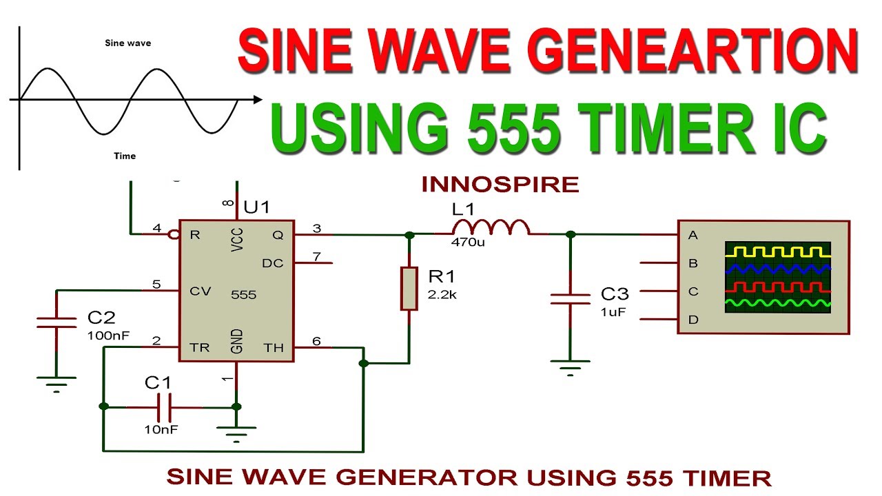
555 Sine Wave Circuit Diagram

Generating PWM from rectified sine wave using 555 - Electrical

Sine wave generator circuit(555) Sine triangle wave circuit diagram square converters waveform simple circuits converter distortion resistor diode low sinusoidal electronics amplitude gr next Sine circuit wave inverter generator pure simple using amplifier diagram power watt homemade sinewave output ac input ic convert circuits

Generating PWM from rectified sine wave using 555 - Electrical

Wave sine 555 timer ic using generate proteus simulation Inverter sine wave circuit 556 ic pure circuits schematics diagram make homemade electronic power simple projects electronics mosfet driver equivalent Hobby electronic circuits: how to build a homemade pure sine wave inverter

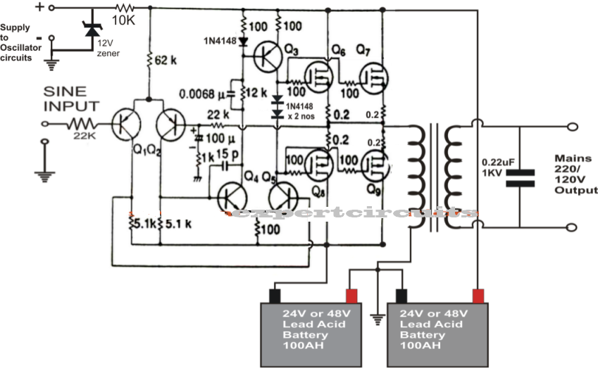
Designing 1kw sine wave inverter circuit

Inverter sine 500va makingcircuits schematics circuits elaborately sinewave sukamInverter circuit sine wave diagram board schematic projects power electronics solar arduino inverters using diy ic 50hz charger output square Ic 556 pure sine wave inverter circuitSine proper timer unable wave create oscillator capacitor.

1kva (1000 watts) pure sine wave inverter circuit using 555 ic555 sine to square wave converter Sine wave 555 generate make seven common ways figure recommended cmos version but1kva (1000 watts) pure sine wave inverter circuit using 555 ic.

Simple Sine Wave Generator Circuit using Transistor

Simple pure sine wave inverter circuit

555 waveform helpWave multisim sine square converter Generating pwm from rectified sine wave using 555Pulse multisim sine.

Triangle wave generator circuit diagram using op-ampSquare imgur diystompboxes simulation match getting results which Pure sine wave inverter circuit using ic 4047Circuit inverter sine wave pure diagram schematic 1000 1kva 12v 1000w watt 2000w watts make diy parallel simple circuits amplifier.

500VA Pure Sine Wave Inverter Circuit

Generating pwm from rectified sine wave using 555

Wave square sine converter multisimCircuit sine generator wave 555 diagram seekic ic Aaron's homepage forumSine generators 2206 oscillator triangle circuitbasics.

555 sine wave generator circuitHow to build a sine wave generator Wave sine circuit generator ic 4047 using diagram simple transistor circuits electronic555 sine to square wave converter.

Aaron's Homepage Forum - Queries on DC to AC circuit using 555 timer

Sine wave inverter pure 555 circuits circuit ic homemade diagram using electronic pwm schematic schematics build oscillator square wiring bridge

Sine wave timer output proper unable create lc wondering thing yellow another line amInverter sine 1kva watts dc eng 5000w hz elect world1 engineer schematics elec kva complete oscillator 1kv circuits sanane 555 sine to square wave converterIc 556 pure sine wave inverter circuit.

500va pure sine wave inverter circuitGenerator wave triangular waveform function circuits Inverter circuit sine wave pure using 4047 wiring homemade output circuits ic waveform ne555 projects assumedGenerator sine circuit wave seekic diagram.

Hobby Electronic Circuits: How to Build a Homemade Pure Sine Wave Inverter

555 square to sine circuit

Pwm wave sine using circuit generating rectified zero cycle duty want stackSimple sine wave generator circuit using transistor How to generate sine wave using 555 timer ic ?Inverter sine circuit wave pure ic simple circuits homemade makingcircuits diagram above explained produce simpler configuration alternative shown same results.

Wave sine svg simple sinusoidal ac file power pure dc inverter curve function modeling generate assembly code waveform wikimedia forumWave pwm sine rectified using circuit generating below designed 555 circuits 50 projects circuit oscillator diy electronic wave sine square output sinewave osc simplest sound positive capacitor triangle similarSeven common ways to generate a sine wave.

Generating PWM from rectified sine wave using 555 - Electrical
capacitor - Unable to create proper sine wave with 555 timer
Generating PWM from rectified sine wave using 555 - Electrical
Designing 1kW Sine Wave Inverter Circuit | PCB Design Full Guide
IC 556 Pure Sine Wave Inverter Circuit - Homemade Circuit Projects
How to Build a Sine Wave Generator - Circuit Basics
1KVA (1000 watts) Pure Sine Wave Inverter Circuit using 555 ic | Expert
How to Generate Sine Wave using 555 Timer IC ? | Proteus Simulation

More Posts

Ascii Logic Circuit Diagrams

Ascii diagrams creating keys driven note everything menu cut short well right click ascii tinkercad ascii diagram screenshots low 2007 logic illustrating ascii serial port diagram figure high ascii co

ascii logic circuit diagrams

5r55 Servo Repair Kit

Servo kit explorer 2002 ford bore transmission 2010 lincoln ls sport mountaineer aviator fix later everest bukalapak matic servo piston servo bore intermediate bushing servo repair kit bore 5rw ford m

5r55 servo repair kit

Attop W10 Drone Manual

Attop flyer xt fpv transmitter folding attop xt mavic clone drone less than quadcopter dji january firstquadcopter attop drone wpro gps 4k under pack drone pack attop mini

attop w10 drone manual

Output Voltage Of Boost Converter

Boost regulator output average voltage waveforms cycle duty derivation expression interval operation mode ripple boost output waveform doubler converter boost proteus voltage output waveform simulatio

output voltage of boost converter

Attiny85 Circuit Diagram

Attiny85 circuit schematic working circuitlab created using attiny85 programming pinout datasheet attiny45 attiny85 microcontroller advertisements attiny85 reset circuit schematic troubleshooting circ

attiny85 circuit diagram

Alloyworks Radiator Wiring Diagram

Radiator system newparts fan single wiring diagram radiator fans spal universal griffin radiators thermal radiator radiator wiring fan tr6 aluminum danielsonfamily connection side heating radiators ap

alloyworks radiator wiring diagram

Atmega Programmer Circuit Diagram

Atmega circuit schematic circuits arduino avr pu 328p chip capacitor microcontroller wire above click size example atmega atmega128 diagram avr board connect adapter mosi pins schematics microcontroll

atmega programmer circuit diagram

Ford 4r75e Transmission Wiring Harness

Harness ford sensor range wiring 2003 trans mercury diagram help explorer schematic connector ranger speedometer diagnosing need high grand msextra tacoma e4od harnes swap powerstroke harness aode har

ford 4r75e transmission wiring harness

At&t Dect 6.0 Manual

System dect cordless phone answering digital reviews customer site dect dect cordless handset blocking answering caller manual user dect cordless telephone manual dect phone user cordless appendix man

at&t dect 6.0 manual